VRayFastSSS2
VRayFastSSS2 Overview
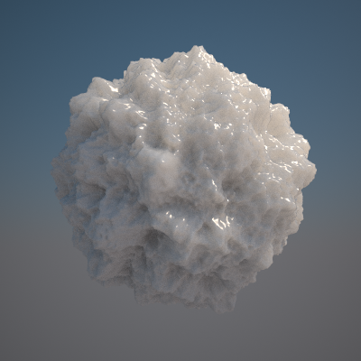
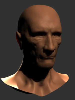
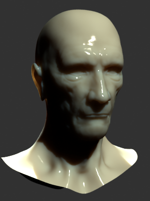
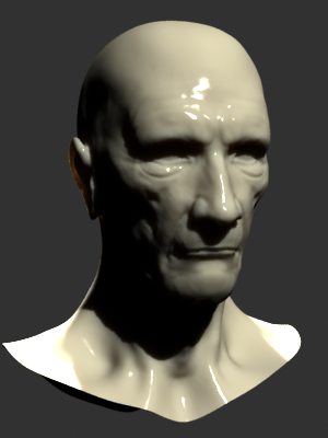
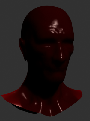
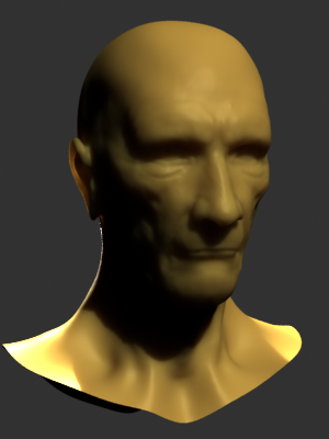
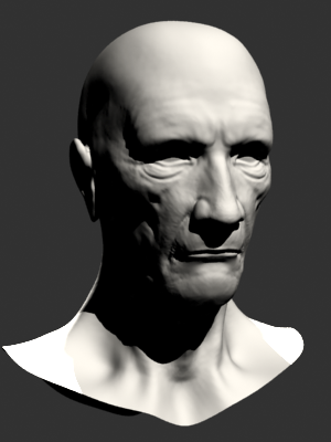
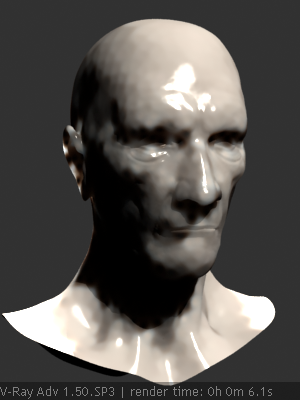
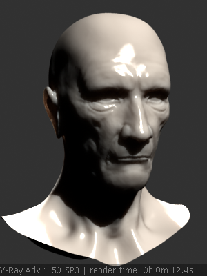
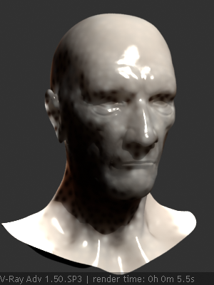
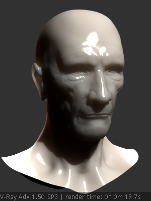
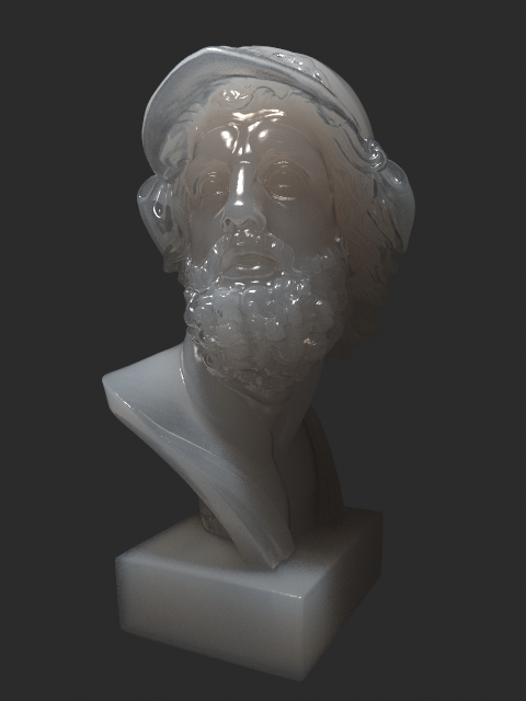
VRayFastSSS2 is a material that is primarily designed for rendering of translucent materials like skin, marble etc. The implementation is based on the concept of BSSRDF originally introduced by Jensen et al. (see the references below) and is a more or less physically accurate approximation of the sub-surface scattering effect, while still being fast enough to be used in practice.
Unlike the original VRayFastSSS material, VRayFastSSS2 is a complete material with diffuse and specular components that can be used directly, without the need of a VRayBlendMtl material. More exactly, the material is composed of three layers: a specular layer, a diffuse layer, and a sub-surface scattering layer. The sub-surface scattering layer is comprised of single and multiple scattering components. Single scattering occurs when light bounces one time inside the material. Multiple scattering results from light bouncing two or more times before leaving the material.
General Parameters
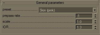
Preset - allows you to choose one of several available preset materials. Most of the presets are based on measured data provided by Jensen et al. in [3].
Example: VRayFastSSS2 Presets
Skin Brown
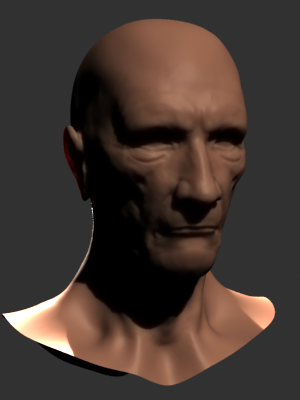
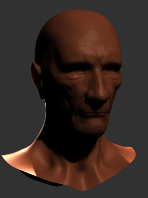
Skin Pink
Skin Yellow
Milk [Skim]
Milk [Whole]

Marble [White]
Ketchup

Cream
Potato
Spectralon
Prepass rate - VRayFastSSS2 accelerates the calculation of multiple scattering by pre-computing the lighting at different points on the surface of the object and storing them in a structure called an illumination map, which is similar to the irradiance map used to approximate global illumination, and uses the same prepass mechanism built into V-Ray that is also used for interpolated glossy reflections/refractions, for example. This parameter determines the resolution at which surface lighting is computed during the prepass phase. A value of 0 means that the prepass will be at the final image resolution; a value of -1 means half the image resolution, and so on. For high quality renders it is recommended to set this to 0 or higher, as lower values may cause artifacts or flickering in animations. If the chosen prepass rate is not sufficient to approximate the multiple scattering effect adequately, VRayFastSSS2 will replace it with a simple diffuse term. This can happen, for example, in objects that are very far away from the, or if the subsurface scattering effect is very small. This simplification is controlled by the Prepass blur parameter.
Example: Prepass Rate
Scatter Radius = 1cm
Prepass = -3

Prepass = -1
Prepass = 0

Prepass = 1
Scatter Radius = 4cm
Prepass = -3

Prepass = -1

Prepass = 0
Prepass = 1
This example shows the effect of the Prepass rate parameter. To better show the effect, the Prepass blur parameter is set to 0.0 for these images, so that VRayFastSSS2 does not replace the sub-surface component with diffuse shading when there are not enough samples. Note how low values of the Prepass rate reduce render times but produce blocky artifacts in the image. Also note that more translucent objects can do with lower Prepass rate values, since the lighting is blurred anyways. In the examples below, when Scatter radius is 4.0 cm, the image looks fine even with Prepass rate of -1, whereas the at this rate, when Scatter radius is 1.0 cm, there are still visible artifacts.
Scale - additionally scales the subsurface scattering radius. Normally, VRayFastSSS2 will take the scene units into account when calculating the subsurface scattering effect. However, if the scene was not modeled to scale, this parameter can be used to adjust the effect. It can also be used to modify the effect of the presets, which resets the Scatter radius parameter when loaded, but leave the Scale parameter unchanged.
Example: Scale
Scale = 1
Scale = 10
Scale = 100
This example shows the effect of the Scale parameter. Note how larger values make the object appear more translucent. In its effect, this parameter does essentially the same thing as the Scatter radius parameter, but it can be adjusted independently of the chosen preset. The images are rendered without GI to better show the sub-surface scattering. The Single scatter parameter was set to Raytraced (solid). The Marble (white) preset was used for all images.
IOR - the index of refraction for the material. Most water-based materials like skin have IOR of about 1.3.
Diffuse and Sub-Surface Scattering Layers
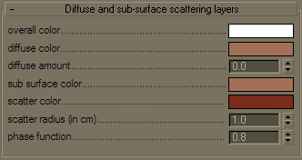 Overall color
- controls the overall coloration for the material. This color serves as a filter for both the diffuse a
nd the sub-surface component.
Overall color
- controls the overall coloration for the material. This color serves as a filter for both the diffuse a
nd the sub-surface component.
Diffuse color - the color of the diffuse portion of the material.
Diffuse amount - the amount for the diffuse component of the material. Note that this value in fact blends between the diffuse and sub-surface layers. When set to 0.0, the material does not have a diffuse component. When set to 1.0, the material has only a diffuse component, without a sub-surface layer. The diffuse layer can be used to simulate dust etc. on the surface.
Sub-surface co lor - the general color for the sub-surface portion of the material.
Scatter color - the internal scattering color for the material. Brighter colors cause the material to scatter more light and thus appear more translucent; darker colors cause the material to look more diffuse-like.
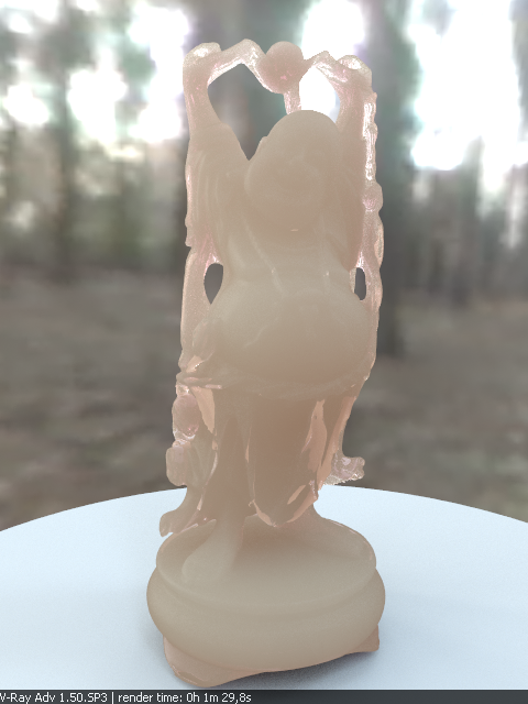
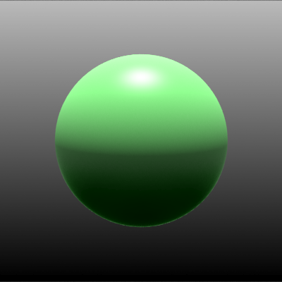
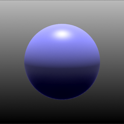
Example: Sub Surface Color & Scatter Color
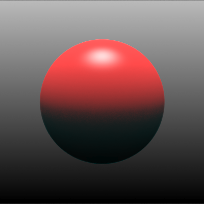
This example shows the effect of and the relation between the Scatter color and the Sub-surface color parameters. Note how changing the Sub-surface color changes the overall appearance of the material, whereas changing the Scatter color only modifies the internal scattering component.
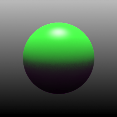
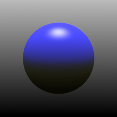
In the first set of images, the Sub-surface color is kept to green, and the Scatter color changes.
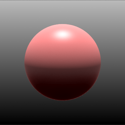
In the second set of images, the Sub-surface color changes, and the Scatter color is kept to green.
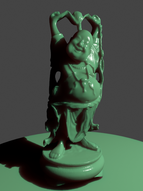
Scatter Color = Red

Scatter Color = Green
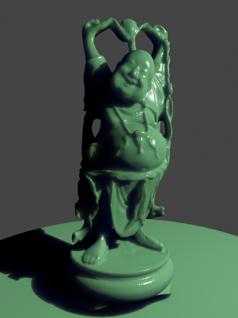
Scatter Color = Blue
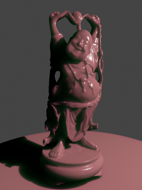
Sub Surface Color = Red
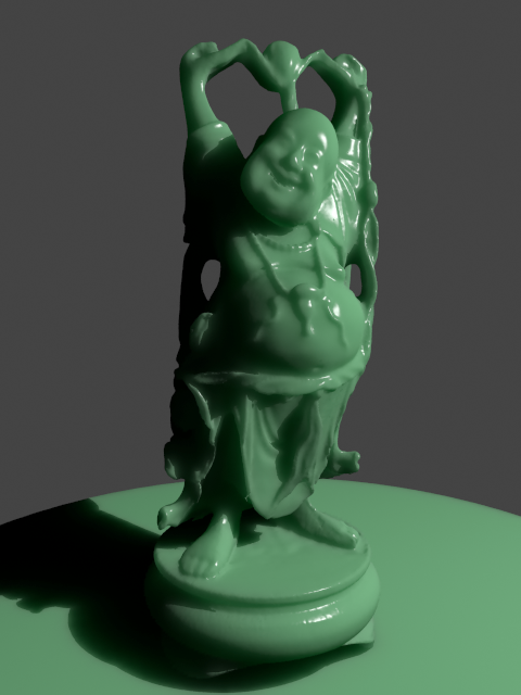
Sub Surface Color = Green
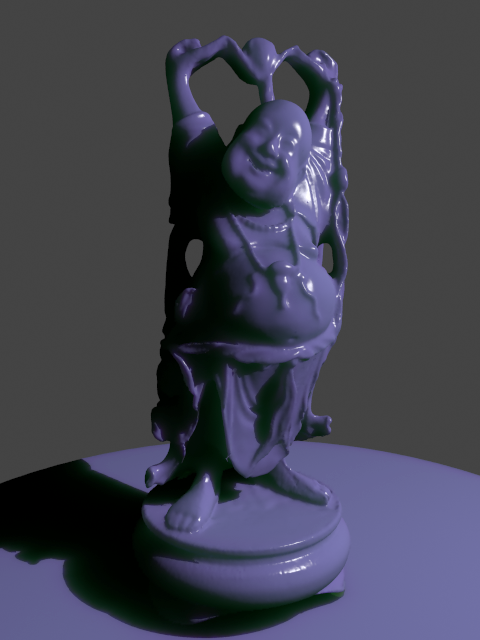
Sub Surface Color = Blue
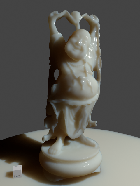
Note: the "happy buddha" model is from the Stanford scanning repository (http://graphics.stanford.edu/data/3Dscanrep/).
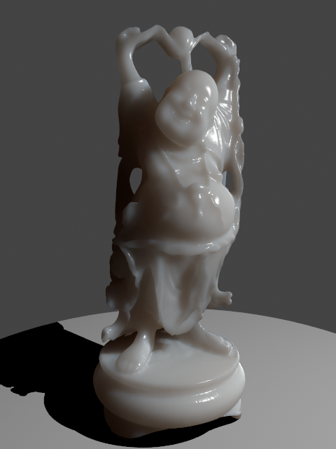
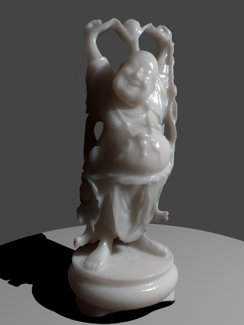
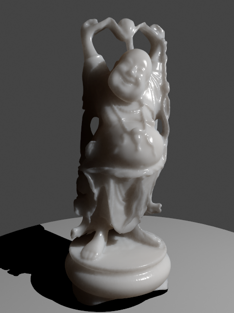
Scatter radius - controls the amount of light scattering in the material. Smaller values cause the material to scatter less light and to appear more diffuse-like; higher values make the material more translucent. Note that this value is always specified in centimeters (cm); the material will automatically convert it into scene units based on the currently selected system units.
Example: Scatter Radius
This example shows the effect of the Scatter radius parameter. Note that the effect is the same as increasing the Scale parameter, but the difference is that the Scatter radius is modified directly by the different presets.
This set of images is based on the Milk (skimmed) preset.
The cube in the lower left corner has a side of 1cm.

Scatter Radius = 1.0cm
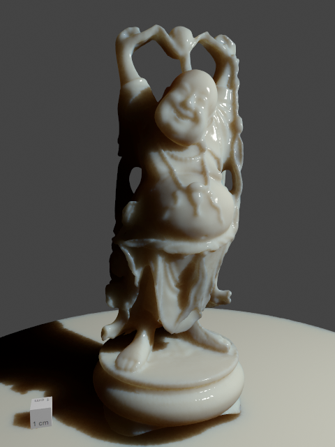
Scatter Radius = 2.0cm
Scatter Radius = 4.0cm
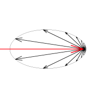
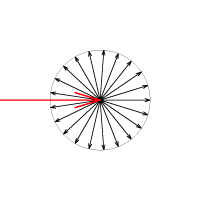
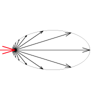
Phase function - a value between -1.0 and 1.0 that determines the general way light scatters inside the material. Its effect can be somewhat likened to the difference between diffuse and glossy reflections from a surface, however the phase function controls the reflection and transmittance of a volume. A value of 0.0 means that light scatters uniformly in all directions (isotropic scattering); positive values mean that light scatters predominantly forward, moving in the same direction that it comes from; negative values mean that light scatters mostly backward. Most water-based materials (e.g. skin, milk) exhibit strong forward scattering, while hard materials like marble exhibit backward scattering. This parameter most strongly affects the single scattering component of the material. Positive values reduce the visible effect of the single scattering component, while negative values generally make the single scattering component more prominent.
Example: Phase Function
This example shows the effect of the Phase function parameter. This parameter can be likened to the difference between diffuse reflection and glossy reflection on a surface, however it controls the reflectance and transmittance of a volume. Its effect is quite subtle, and mainly related to the single scattering component of the material.
The red arrow represents a ray of light going through the volume; the black arrows represent possible scattering directions for the ray.
Phase Function = -0.9 (Backward Scattering)
More light comes out.
Phase Function = 0 (Isotropic Scattering)
More light exits object.
Phase Function = 0.0 (Forward Scattering)
More light is absorbed object.
Phase Function = -0.5 (Backward Scattering)
Phase Function = 0 (Isotropic Scattering)
Phase Function = 0.5 (Forward Scattering)
Specular Layer
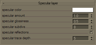 Specular color
-
determines the specular color for the material.
Specular color
-
determines the specular color for the material.
Specular amount - determines the specular amount for the material. Note that there is an automatic Fresnel falloff applied to the specular component, based on the IOR of the material.
Specular glossiness - determines the glossiness (highlights shape). A value of 1.0 produces sharp reflections, lower values produce more blurred reflections and highlights.
Specular subdivs - determines the number of samples that will be used to calculate glossy reflections. Lower values render faster, but may produce noise in the glossy reflections. Higher values reduce the noise, but may take longer to calculate.
Specular reflections - enables the calculations of glossy reflections. When off, only highlights will be calculated.
Specular trace depth - the number of reflection bounces for the material.
Options
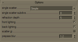 Single scatter
- controls how the single scattering component is calculated:
Single scatter
- controls how the single scattering component is calculated:
-
None - no single scattering component is calculated.
-
Simple - the single scattering component is approximated from the surface lighting. This option is useful for relatively opaque materials like skin, where light penetration is normally limited.
-
Raytraced (solid) - the single scattering component is accurately calculated by sampling the volume inside the object. Only the volume is raytraced; no refraction rays on the other side of the object are traced. This is useful for highly translucent materials like marble or milk, which at the same time are relatively opaque.
-
Raytraced (refractive) - similar to the Raytraced (solid) mode, but refraction rays are traced as well. This option is useful for transparent materials like water or glass. In this mode, the material will also produce transparent shadows.
Example: Single Scatter Mode
This example shows the effect of the Single scatter mode parameter.
For relatively opaque materials, the different Single scatter modes produce quite similar results (except for render times). In the following set of images, the Scatter radius is set to 0.5 cm.
In the second set of images, the Scatter radius is set to 50.0 cm. In this case, the material is quite transparent, and the difference between the different Single scatter modes is apparent. Note also the transparent shadows with the Raytraced (refractive) mode.
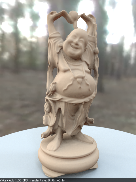
Single Scatter = Simple

Single Scatter = Ray Traced Solid

Single Scatter = Ray Traced Refractive
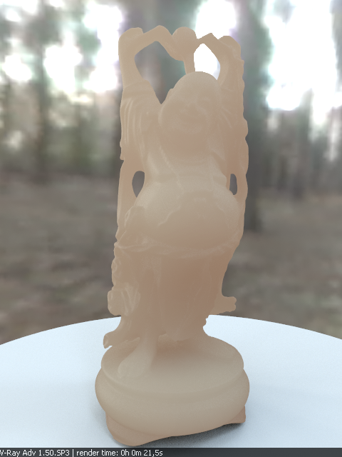
Single Scatter = Simple
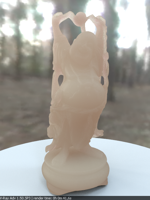
Single Scatter = Ray Traced Solid
Single Scatter = Ray Traced Refractive
Single scatter subdivs - determines the number of samples to make when evaluating the single scattering component when the Single scatter mode is set to Raytraced (solid) or Raytraced (refractive).
Refraction depth - this determines the depth of refraction rays when the Single scatter parameter is set to Raytraced (refractive) mode.
Front lighting - enables the multiple scattering component for light that falls on the same side of the object as the camera.
Back lighting - enables the multiple scattering component for light that falls on the opposite side of the object as the camera. If the material is relatively opaque, turning this off will speed up the rendering.
Scatter GI - controls whether the material will accurately scatter global illumination. When off, the global illumination is calculated using a simple diffuse approximation on top of the sub-surface scattering. When on, the global illumination is included as part of the surface illumination map for multiple scattering. This is more accurate, especially for highly translucent materials, but may slow down the rendering quite a bit.
Prepass blur - controls whether the material will use a simplified diffuse version of the multiple scattering when the prepass rate for the direct lighting map is too low to adequately approximate it. A value of 0.0 will cause the material to always use the illumination map. However, for objects that are far away from the camera, this may lead to artifacts or flickering in animations. Larger values control the minimum required samples from the illumination map in order to use it for approximating multiple scattering.
Example: Color Changes Inside the Material
This example demonstrates how the apparent color of the material might change inside of objects. In the first set of images, the Scatter color is set to grey, while the Sub-surface color changes between red, green and blue. Note how the part of the surface that is directly lit appears with the Sub-surface color, while the portion of the object away from the light gradually blends into darkness. This is because the light colors specified by the Sub-surface color parameter are scattered out of the material near the surface, and only the remaining light passes through. (To better demonstrate this effect, the Single scatter mode is set to Raytraced (solid) for all images in this example.)
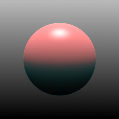
The Sub-surface color is red (RGB 218, 58, 58)
and the Scatter color is grey.
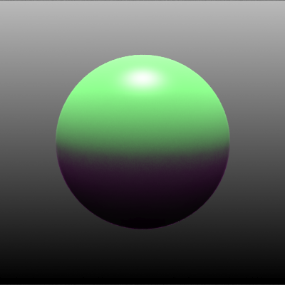
The Sub-surface color is green (RGB 58, 218, 58)
and the Scatter color is grey.
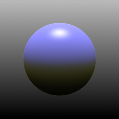
The Sub-surface color is blue (RGB 58, 58, 218)
and the Scatter color is grey.
This effect becomes less apparent if the colors are more saturated, as demonstrated in the following set of images:
The Sub-surface color is red (RGB 218, 13, 13)
and the Scatter color is grey.
The Sub-surface color is green (RGB 13, 218, 13)
and the Scatter color is grey.
The Sub-surface color is blue (RGB 13, 13, 218)
and the Scatter color is grey.
If this effect is not desired, the Scatter color should be modified. In the set of images below, the Sub-surface color is set as before, and in addition, the Scatter color is set to a more saturated version of the same color.
 The Sub-surface color is (RGB 218, 58, 58)
and the Scatter color is (RGB 218, 13, 13).
The Sub-surface color is (RGB 58, 218, 58)
and the Scatter color is (RGB 13, 218, 13).
The Sub-surface color is (RGB 58, 218, 58)
and the Scatter color is (RGB 13, 218, 13).
Notes
-
When using either Raytraced (solid) or Raytraced (refractive) mode for the Single scatter parameter, you need to use VRayShadows for standard lights in order to get correct results.
-
VRayFastSSS2 uses the V-Ray prepass system to simulate and interpolate the sub-surface scattering. During other GI calculations (e.g. light cache or photon mapping), the material is calculated as a diffuse one.
-
For the reason explained above, VRayFastSSS2 will render as a diffuse one with the progressive path tracing mode of the light cache.
References and Links
Here is a list of links and references used when building the VRayFastSSS2 material.
-
[1] H. C. Hege, T. Hollerer, and D. Stalling, Volume Rendering: Mathematical Models and Algorithmic aspects
An online version can be found at http://www.cs.ucsb.edu/~holl/publications.html
Defines the basic quantities involved in volumetric rendering and derives the volumetric and surface rendering equations. -
[2] T. Farrell, M. Patterson, and B. Wilson, A Diffusion Theory Model of Spatially Resolved, Steady-state Diffuse Reflectance for the Noninvasive Determination of Tissue Optical Properties in vivo, Med. Phys. 19(4), Jul/Aug 1992
Describes an application of the diffusion theory to the simulation of sub-surface scattering; derives the base formulas for the dipole approximation used by Jensen et al. (see below). -
[3] H. Jensen, S. Marschner, M. Levoy, and P. Hanrahan, A Practical Model for Subsurface Light Transport, SIGGRAPH'01: Computer Graphics Proceedings, pp. 511-518
An online version of this paper can be found at http://www-graphics.stanford.edu/papers/bssrdf/
Introduces the concept of BSSRDF and describes a practical method for calculating sub-surface scattering based on the dipole approximation derived by Farrell et al. (see above). -
[4] H. Jensen and J. Buhler, A Rapid Hierarchical Rendering Technique for Translucent Materials, SIGGRAPH'02: Computer Graphics Proceedings, pp. 576-581
An online version of this paper can be found at http://graphics.ucsd.edu/~henrik/papers/fast_bssrdf/
Introduces the idea of decoupling the calculations of surface illumination and the sub-surface scattering effect in a two-pass method; describes a fast hierarchical approach for evaluating subsurface scattering and proposes a reparametrization of the BSSRDF parameters for easier user adjustment. -
[5] C. Donner and H. Jensen, Light Diffusion in Multi-Layered Translucent Materials, SIGGRAPH'05: ACM SIGGRAPH 2005 Papers, pp. 1032-1039
An online version of this paper can be found at http://graphics.ucsd.edu/papers/layered/
Provides a concise description of the original BSSRDF solution method presented by Jensen et al; extends the model to multi-layered materials and thin slabs using multipole approximation.